Important: In order to prevent accidents, read the operating instructions before commissioning and use.
Always keep the operating instructions available by the machine !
CE-Confirmation
for Universal Fret Saws/Scroll Saws
Type: MULTICUT-1 MULTICUT-2S MULTICUT-SE MULTICUT-QUICK
- EC-Regulation 89/392/EEC (machine standards), latest alteration by EC-standards 93/68
- EC-Regulation 73/23/EEC (low voltage standards), latest alteration by EC-standards 93/68
- EC-regulation 89/336/EEC (electromagnetic compatibility), latest alterion by EC standard 93/68
The following rules were applied to when constructing and building the machines:
|
Harmonised standards:
- EN 292-1
- EN 349
- EN 292-2
- EN 60204-1
- EN 294
European Standards and Standard Designs:
- EN 60529
- prEN 31020
- EN 954
- EN DIN 50081-2
- EN ISO 23746
- EN DIN 50082-2
National Standards and Standard Designs:
Electronic emission according to:
EN 55014:1993= DIN EN 55014 /VDE 0875 Part 14
EN 60555 Part 2 and Part 3:1987 |
|
Immunity from interferences according to: EN 55014:1995
The above machine was tested according to paragraph 3 of the GSG (safety security law) and a "GS-Certificate with the number 031037" was issued by:
Fachausschun holz
PrUf- and Zertifizierungsstelle im BG-PRUFZERT
Vollmoellerstrasse 1
D-70563 Stuttgart
Hegner Prazisionsmaschinen GmbH
VS-Schwenningen, 1st November, 1997
roghammer Manager

|
Preface
The machines
- Multicut-1
- Multicut -2S
- Multicut-SE
- Multicut-Quick
are designed for professional as well as private use.
The machines have been designed exclusively for the sawing of wood, plastics, non-ferrous metals, soft iron and mild steel by means of fret saw and piercing sawblades with a length of 130mm (5 in).
This manual of operating instructions is designed to acquaint you with the knowledge required for the commissioning and use of the machine.
You will find important information on the safe handling and proper use of the machine.
Please read these Instructions carefully and take special note of the guidelines and warnings!
In case of improper use of the machine and non-observance of the warnings and guide-lines given in these operating instructions, the manufacturers warranty is invalidated.
If you have any questions after reading these operating instructions, please contact your dealer.
Hegner Prazisionsmaschlnen GmbH
Symbols and their meaning
- This symbol marks text with very important information and in many cases gives information for your safety! It is absolutely necessary that you take note of this Information!
- This symbol points to texts containing comments, guidelines or tips. It refers to a chapter, sub-chapter, page or picture.
- This symbol points to references to supple-mentary information about the current topic.
- This dot marks the description of operations which you should carry out.
|
Index :
| 1.0 |
Technical information |
| 2.0 |
Delivery of the machine |
| 3.0 |
Operating instructions |
| 4.0 |
Machine use |
| 5.0 |
Guidelines |
| 6.0 |
Remaining risks |
| 7.0 |
Unpacking / Setting up |
| 8.0 |
Commissioning / Decommissioning |
| 9.0 |
Changing sawblades |
| 10.0 |
Sawblade change with internal cuts |
| 11.0 |
Swivelling the table |
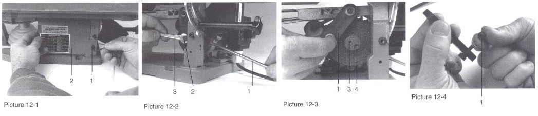
| 12.0 |
Adjusting the stroke length |
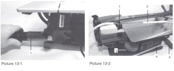
| 13.0 |
Connecting a dust extractor |
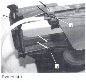
| 14.0 |
Maintenance / Cleaning |
| 15.0 |
Repairs / Spare parts |
| 16.0 |
Application guide lines |
| 17.0 |
Speed selection |
| 18.0 |
Operating problems and their causes |
1.0 Technical Characteristics
Multicut-1
|
| Depth of throat |
365 mm |
| Cutting clearance |
50 mm |
| Maximum depth of cut (wood) |
50 mm |
| Size of table |
435 x 230 mm. 45° swiveling |
| Depth & width |
520 x 270 mm |
| Blade stroke length |
12 and 15 min |
| Motor |
230V-. 50Hz. 100Watt power output |
| Weight |
approx. 16 kg nett |
| Blade length |
130 mm (5 in) |
| Suction pon |
o 35 mm |
| Mains fuse |
3 A Or 5 A fuse |
Multicut-2S/SE
|
| Depth of throat |
460 mm |
| Cutting clearance |
65 mm |
| Maximum depth of cut (wood) |
65 mm |
| Size of table |
435x230 mm. 454/12? swivelling |
| Depth & width |
610x280 mm |
| Blade stroke length |
12 and 19mm |
| Motor |
230V-BOHz.100Watt power output |
| Weight M2S/ SE |
approx. 19 Kg nett/ 23 Kg nett |
| Blade length |
130 mm |
| Suction port |
0 35 mm |
| Mains fuse |
3 A or 5 A fuse |
Multicut-Quick
|
| Depth of throat |
560 mm |
| Cutting Clearance |
65 mm |
| Maximum depth of cut (wood) |
65 mm |
| Size of table |
435x230 mm 459/129 swivelling |
| Depth & width |
730x290 mm |
| Blade stroke length |
12 and 19mm |
| Motor |
230V- 50Hz. 100Watt power output |
| Weight |
approx. 29 Kg nett |
| Blade length |
130mm |
| Suction port |
0 35 ram |
| Mains fuse |
3 A or 5 A fuse |
|
1.1 Ratings for the extraction system
Exhaust volume when fitted to 0 35mm hose: 70 m3
Existent depression with an air speed of 20m/s: 1666 Pa
The dust emission values, measured according to the precepts for the testing of the dust emission (workpost-related dust concentration) of wood working machines of the professional comittee for wood, are distinctly under the presently valid limit of 2.0 mg/m3.
1.2 Emission of Noise
Measurement Conditions:
- prEN 31202 for the workpost-related emission values.
- With the following supplements determined by TC 142 in order to obtain an exactness class better than 3 dB.
- The environmental correction factors K2A respectively K3A are < 4dB.
- The difference between extraneous noise sound level and noise sound intensity level is < 6 dB each metering point.
- K3A is calculated according to annex A, prEN 31204.
- An ashlar-type enveloping surface with 9 metering points is utilised in a distance of 1 m from the reference surface.
Workpiece: pine wood; dimensions 150 x 100 x 20mm (sanded all over)
Tool: Fret Saw Blade Dimensions: depth 1,5 mm, width 1 mm. The determined noise emission values are:
Acoustic capacity level [ dB (A) ]
Idle running: 64,1 dB
Machining: 74,5 dB
Statement to the noise emission levels: The given values are emission levels and do not correspond in every case to the save working place related values. Although there is a relation between emission and imission levels, it is perhaps necessary to take additional safety measures. Factors which have a certain influence to the actual imission level are the duration of the exposure, the kind of work-shop and some other influences. The acceptable limits do also depend on the different countries. This information should give a better possibility to the user of the machine to classify the hazards and risks.
Source: EN 292-Part 2
The real noise emission can deviate from the given values in a range of 4 dB(A) due to specific influences of the workshop.
2.0 Delivery of the machine
- Check the machine upon receipt
- Damage to the machine
- Contents against delivery note
- Examine the packaging for small parts
If there is any damage or discrepancies contact your supplier immediately!
3.0 Operating instructions
Read the operating instructions carefully before commissioning and using the machine. If the machine is not used in accordance with the operating instructions the manufacturers warranty is void.
4.0 Machine use
- This machine has been designed for the sawing of wood, plastics, non-ferrous metals and mild steel by means of fret saw (scroll saw) and piercing sawbiades 130mm (5 in) long.
- Use for any other purpose has not been catered for.
- This machine must only be used by persons who have read these instructions and are familiar with the safety requirements and dangers associated with its use.
- The relevant safety procedures outlined in these instructions must be observed.
- Only original HEGNER spare parts must be used.
- Damage which occurs due to the use of spare parts which are not original HEGNER parts, will invalidate the manufacturers warranty.
- Modifications to the machine or usage for any purposes than those for which the machine was designed will invalidate any liability of the manufacturer.
5.0 Safety guidelines
5.1 General safety guidelines
-Keep people other than the operator away from the machine. Children should only be allowed to use the machine under super-vision.
-Do not touch any moving parts.
5.2 Commissioning
- Check that the voltage on the motor plate corresponds with the voltage of the electricity supply.
- Connect a dust extractor. 13.0 Connecting a dust extractor
- Check work area is well ventilated.
|
5.3 The operator
- In order to minimise the risk of accident with the machine, read the operating instructions carefully.
- Never work under the influence of drugs, alcohol or medicine.
- Never use loose fitting clothing. Always use eye goggles.
- Do not wear jewellery.
5.4 Before starting work
- Insure that the machine is switched off. 8.3 Switching the machine off
- Insure that the fitted sawblade is appropriate for the work.
- Check that the sawblade is tensioned
- Check that all appropriated guards are fitted correctly.
5.5 During work
- Only remove swarf dust and chips when the machine is switched off.
- In case of a power failure return the power switch to the OFF position.
5.6 After work
- Switch the machine off and pull the mains plug.
6.0 Remaining risk
Even when adhering to all the relevant safety rules the following remaining risks can occur because of the nature of the machine.
- Touching the sawblade
- Breakage of the sawblade
- Touching live parts due to
- damaged terminal box
- damaged capacitor
- damaged cable
- Hearing impaired due to working for long periods without ear protection.
- Inhaling dust and endangering your health.
|
7.0 Unpacking & setting up
7.1 Unpacking
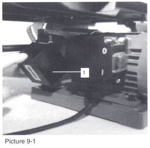
- Picture 7-1
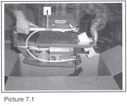
- Lift the machine out of the packing as shown in the picture.
- Do not lift by the upper arm (1)
7.2 Setting up
- Picture 7-2
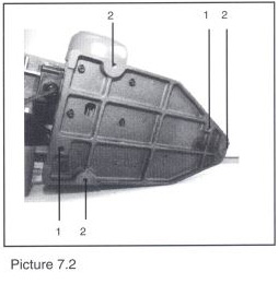
- Place the machine on a stable surface which is solidly constructed and without loose joints with room to approach the machine from the front with plenty of free space.
- The height of the surface should be sufficient to allow the operator to use the machine with his/her back in an upright position. The elbow of the operator should be at the height of the machine table surface.
- Secure the machine to the surface
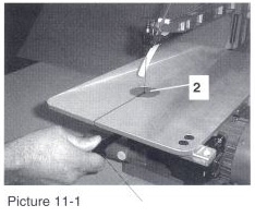
- either with two coach screws, secured from the top through the two holes (1) in the baseplate of the machine
- or with 3 M10 bolts screwed through from under the mounting surface into the threated holes (2). We recommend our machine stand (optional acces-sory), especially constructed for our fret saws.
7.3 Ambient conditions
The machine should be installed in a place which is
- vibration free
- dry
- free from gas and vapour
- free from mineral dust
- well ventilated
7.4 Electrical installation
The electrical power supply must conform to the stan-dards required by law and match the power requirements of the machine!
- 1.0 Technical Characteristics
- Make sure that the mains switch on the machine Is in the OFF position!
- 8.3 Switching the machine on
- Connect the mains plug to the supply socket.
Make sure that the lead
- does not foul the work
- will not cause operator to trip up
8.0 Commissioning/De-commissioning
8.1 Commissioning the machine
We assume that
- you have read the proceeding instructions (particularly 5.0 Safety guidelines). If not, please do it now before proceeding from here!
- the machine has been installed and connected to the mains properly
- that all tools and materials have been removed from the work area
- the machine is undamaged and correctly mounted.
- Check that the clamped in sawblade is straight!
- A bent sawblade is unserviceable and should be nw replaced with a new one.
- 9.0 Changing a sawblade
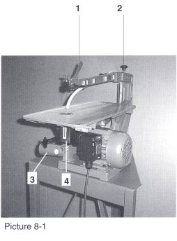
8.1.1 Tensioning the sawblade
- Picture 8-1
- Check that the quick action blade tensioning lever (1) is in the tensioned position. (Not with the Multicut-1 machine)
- Tension the sawblade using the tensioning knob (2)
Turn the tensioning knob (2) clockwise to increase the tension until the blade is tensioned. When the blade is tensioned correctly you should be able to move the blade about 1mm forward and back at table level.
|
8.1.2 Untensioning the sawblade
- Picture 8-1
- Untension the sawblade only when the machine is switched off!
Untension the sawblade by pulling the quick action tension lever (1) forward on the Multicut-2S, -SE and Quick. On the Multicut-1 turn the tensioning knob (2) about three complete turns anti-clockwise.
8.1.3 Vacuum cleaner /dust extraction system
- Picture 8-1
Put the end of the dust extractor hose into the tapered pod (3) so that it fits tightly.
- Take care that protection hood (4) is folded upwards!
8.2 Switching the machine on
- Picture 8-3
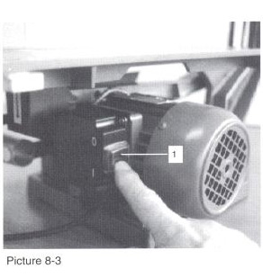
Attention: The machine will start to function as soon as it is switched on!
- Remove all tools, workpieces, dust and debris from the work table!
- Connect the machine to the mains supply and switch on the machine with the main switch (1) pressing the rocker at the bottom ( I ).
- Switch on the dust extractor.
8.3 Switching the machine off temporally
- Picture 8-4
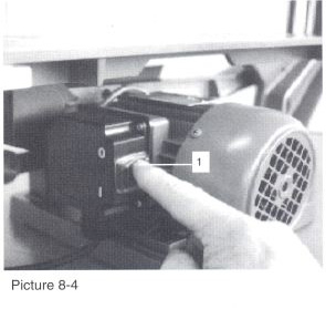
- Switch the machine off using the main switch (1) by pressing the rocker at the top (0) .
- Switch off the dust extractor.
- Remove all tools, workpieces, dust and debris from the work areal
8.4 Taking the machine out of operation
when you have finished using the machine and are leaving the workshop
- Ensure that the machine is switched off at the main switch (1) by pressing the rocker at the top (0) and isolate from the power supply.
- Untension the sawblade.
- Remove all tools, workpieces. dust and debris from the work area!
|
14.2 Sight check
- Carry out a visual check at regular inter-vals with the machine switched off. Check all parts of the machine, especially
- the mains plug
- the mains cable
- the switch box for damages !
- If damage is found, take the machine out of operation immediately and have an expert repair made with original spare parts!
14.3 Cleaning
- the machine should be cleaned regularly when required!
- dust and chips should not be allowed to Ur accumulate on the machine!
14.3.1 Taking the machine out of operation
- 8.4 Taking the machine out of operation
14.3.2 Cleaning the machine
- Clean the machine by removing the dust and chips with a vacuum cleaner.
- Remove the side guard plate and remove the dust and chips accumulating behind it.
- Remove any remaining accumulations with a soft brush ( a paint brush is ideal).
- Do not use any
- combustible
- etching
- scouring
cleaning agents!
- Prevent liquid or dampness from penetra-ting into the machine, especially to the electrical parts!
- If liquid or dampness has penetrated the electrical parts do not connect the ma-chine to the electrical supply!
- In this case contact your dealer, distributor or the manufacturer.
|
15.0 Repair/Spare Parts
- This instruction manual does not contain any in-structions for repairs! The repair and/or exchange of parts is done at your own risk!
- Please observe the following guidelines without fail.
15.1 Repairs
- Do not repair or replace any defective elec-trical parts!
- These parts must be replaced by original parts from the manufacturer!
- The replacement of electrical parts must only be carried out by the manufacturer, authorised dealer /distributor or a qualified operative (e.g. electrician).
- An Improper repair or replacement of electrical parts may cause death or injury due to electrical shock or cause electrical fires!
The person repairing the machine is held liable for all injuries caused in this way!
- Defective mechanical machine parts
-should normally be replaced only by the manufacturer/dealer/distributor or an operative with the relevant mechanical knowledge
- can be exchanged by the user with origi-nal parts from the manufacturer. if the user has the required mechanical knowlege.
- The person repairing the machine is held liable for all injuries or damage caused by improper repair!
- If you want to repair the machine yourself,
- switch off the machine and unplug from the electrical supply before commencing repair.
|
16.0 Application guidelines
16.1 Choice of sawblade with regard to the material to be cut
- Table on the side guard plate of the machine
- Important:
When sawblades become blunt they should im-mediately be replaced with a new sawblade. This applies particularly when cutting iron or steel. The full cutting capacity and precision is only achieved if the recommended quality and grade of sawblade is used.
- Useful guide:
Br If for economic reasons you wish to continue to use a sawblade that is becoming blunt, you can fix, with double sided tape, a false table of at least 20mm thickness to the machine table and continue sawing on top of this. This way you can use the portions of the sawblade not used pre-viously.
- Working with plastic materials:
12T To stop the plastic fusing together behind the sawblade, cover the desired cutting line with brown parcel tape or another adhesive PVC tape.
16.2 Feed pressure
The feeed pressure you apply to the workpiece must be directed towards the front of the sawblade. Failure to do this will cause the work-piece to chatter or break the sawblade. Some thick workpieces require a strong feed pressure!
16.3 Use of a fence
It is not possible for a fretsaw (scrollsaw) to be used with a fence.
If you attempt to use the fretsaw (scrollsaw) with a fence the blade will depart from the desired cutting line and break as side pressure is ap-plied to the blade. This is due to the right hand bias of all fretsaw and piercing sawblades.
Exact sawing is achieved by
- a sharp sawblade a thin,
- clear cutting line,
- good lighting
16.4 Straight cuts
Hold the workpiece inclined to the right of the table about 19 to 59 (The angle depends on the material, the type and sharpness of the sawblade and the blade tension).
|
16.5 Guidance for cutting metals
- Remove any burrs from the edges of metal workpieces. Ensure that all sides are smooth.
- Attach small or thin workpieces (e.g. thin sheet metals) to a plywood or hardboard panel about 5mm thick, with double sided adhesive tape. Alternatively place the work-pieces between two plywood pieces that are bolted together so that the workpiece cannot shift.
- Saw the workpiece and the plywood together (beware using a blade which is too coarse.)
- Select wood sawblades for
- soft non-ferrous metals e.g.
- aluminium sheet
- soft copper sheet
- soft brass sheet
Use grades 1, 5 or 9 from the sawblade pack depending on the thickness of metal to be cut.
- It is advisable to wipe the cutting line with light lubricating oil before sawing.
- Select metal sawblades for
- hard non-ferrous metals and ferrous metals e.g. 111F
- duralumin sheet
- hard brass sheet
- steel sheet
- Use grades 1, 5 or 9 from the sawblade pack depending on the thickness of metal to be cut. For thick sheet of 10mm thickness it is better to use number 12 (or higher) metal cutting sawblades.
- Smear cutting oil or paste around the cutting line before starling to saw.
Despite using blades of best quality iron and steel wear out sawblades quicker, depending on the degree of hardness.
17.0 Selection of cutting speed (variable speed machines only)
- Higher speeds are preferred for cutting most LW, timber and plastics.
- Slower speed is best used on metals. thin materials or extremely fine, intricate fret work.
- High speeds give better cutting performance: slower speeds give greater blade life. This trade-off should always be considered when selecting cutting speed.
|